
Define Dumps
To access this screen:
-
Design ribbon >> Dump Modelling >> Define Dumps.
This screen is used for setting up your project dumps and lifts for automated design. This step is a mandatory part of the process to design a dump in Studio OP.
The Dump Definition panel is used to define each dump within your current project.
As with all managed tasks, updates made on this panel are committed to your project using the Save (1) or Save and Close (2) buttons at the top of the form. You can also Close without saving (3).
Note: You can add a topography
to a dump after it has been created (and even designed). Once
added, the lowest lift toe string (and mid position and height)
will be automatically adjusted the next time design strings
are recreated in the Auto
Dump Design task.
Activity steps:
-
Display the Define Dumps screen.
-
Review and edit the Dump Table. This is the uppermost table on this screen, and summarizes all dumps currently defined for the active project.
Note: One dump will always be present for a pit ("Dump 1") and if an attempt is made to delete the sole remaining dump, a default dump will be reinstated.
-
Add a new row to the table using Dumps >> Create.
-
Duplicate the currently selected row using Dumps >> Copy.
-
Delete the currently selected row using Dumps >> Delete.
The table columns are:
-
Label – Editable field showing label text used to identify the dump in the Task window.
-
Topography – If a local topography wireframe file has been associated with the dump (see below) its name appears here.
-
Link – Where the topography is a link file to a remote location (see below), Yes displays, otherwise No.
-
Topography Path – The fully-qualified path to the local or remote topography file.
-
-
Topography – Topographies are defined by file selection and is performed independently of any topographies set up using the task (although you can still select a file or link to a file that is already defined for the pit if you wish). Dump topographies are optional but recommended for accurate evaluation results. To associate a topography with a dump, select an existing table row then either:
-
Add copy – Create a copy of an external topography file in the current database or;
-
Add Link – Create a link file in the database that references a file at a remote location.
Remove – Disassociate the currently assigned topography from the dump.
-
-
Edit or review the Lift Table. This table describes all lifts for the currently selected dump. This table updates automatically when the selection above changes. Define the contents of the table using the following controls:
-
Crest elevation – The starting elevation of the crest of the lowest lift.
-
Lift height
-
No. of lifts
Lifts are defined by number, starting from the lowest possible Crest elevation. In the first instance, lifts are generated using Lift height x No. of lifts.
-
-
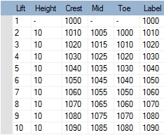
Click Apply to add the lift records to the table. The table is then populated with lifts shown with increasing elevation in a top-bottom order using , for example:
Note: Use Clear all lifts to clear the current lift table ready for a new definition. You will need to confirm this action, which cannot be undone.
-
Configure your Label options. By default, dump lifts are labelled with their Crest value, but you can choose to label them with the Toe elevation value, Mid point value or Lift number instead.
Related topics and activities